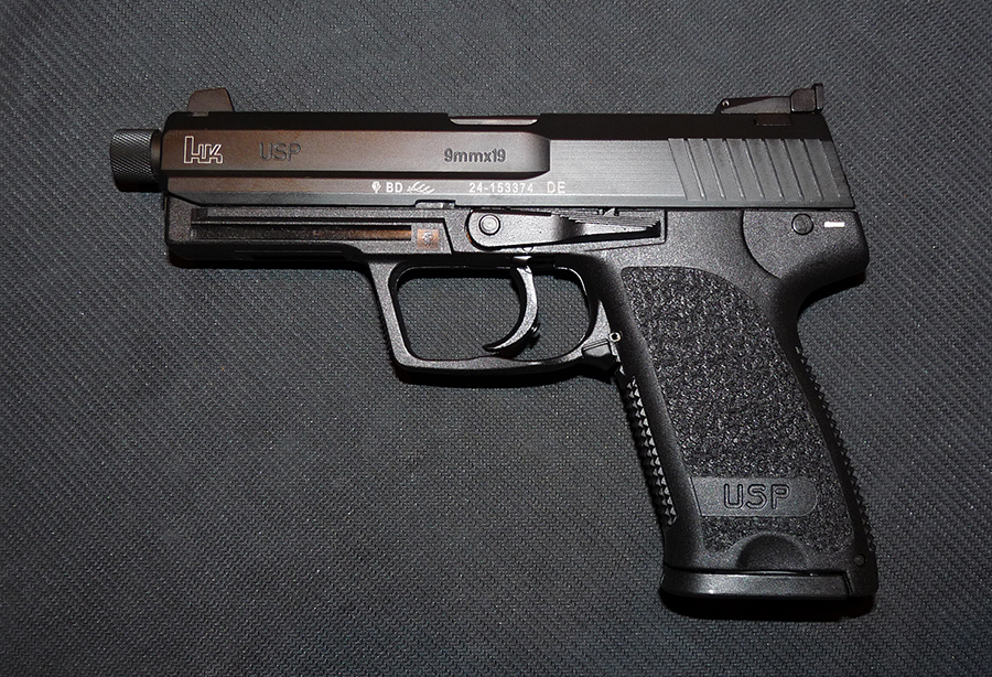
This short guide will show you how to install the Match LEM Hybrid Trigger in your USP full-size. This trigger combines various parts from the Match Trigger and LEM kits and is, reportedly, the best H&K trigger available.
The same guide can be used to install the kit on a USP Compact, HK45, or HK45 Compact. Note that if you are installing the kit on a compact or HK45, you will not be able to use the trigger that comes with the Match Trigger kit. In addition, there is very little room behind the trigger on the compacts so the overtravel screw does not help. To install the Match trigger on a full-size HK45, you will have to drill and tap the stock trigger to fit the overtravel stop screw, or shave down the trigger to fit. You can also send your stock trigger to Bill Springfield to have it drilled and tapped for $20. Bill will provide a stop screw with the service.
Parts can be purchased directly from HK Customer Service (706-568-1906, press 1 for Consumer Support, then 2 to order parts), Cross Creek Guns, Numrich, HKParts.net, TopGunSupply, Midwestgunworks, Brownells, EuroOptic, or other online vendors. It will be most cost effective to purchase the complete LEM Kit and only parts of the Match Trigger Kit (not the complete Match Trigger Kit) because you will not be using the Match hammer and it is the most expensive part of the Match Trigger Kit.
If you reside within the state of Texas and would like to perform this conversion but feel uneasy about taking apart the pistol and putting everything back together, send me a PM. I might be able to offer some assistance.
Important Notes
• If you are installing the kit on an older model USP Compact or HK45 (date code of BB=2012 or earlier), you may not need to swap out the stock hammer spring as their stock hammer spring is the Match spring. Later models of these 2 guns no longer come with the Match hammer spring. The easiest way to tell if your gun has the Match hammer spring is to remove the magazine and look at the existing hammer spring in the magwell. If it is Blue (see pic below), you do not have the Match spring.

• If your gun is already a LEM (Heavy or Light), you will not need parts 7 thru 12 in the picture below.
• If your gun already has the Match trigger (e.g.: Tactical, Expert, Elite, etc.) then you will only need parts 8 thru 12 (or the complete LEM kit) and part 7 if your date code is pre 2005 (AF). You may need parts 5 and 6 on newer Tactical models.
Parts Required
1. Match Trigger (215684)
2. Overtravel Stop Screw (215680)
3. Hex Wrench for Stop Screw (958179)
4. Light TRS (209266)
5. Match Hammer Spring (215694)
6. Match Nickel-Plated Flat Sear Spring (215691)
7. Catch (219442 - only needed if your gun's date code is early AF=2005 or earlier)
8. LEM Sear (219439)
9. LEM Hammer (219452)
10. LEM Cocking Piece (219443)
11. LEM Cocking Piece Spring (219444)
12. LEM Hammer Axle (214258)

If you want to retain the safety function (and thus the Safety Lever), you will need a V5+6 Detent Plate (or re-use your stock V1+2 Detent Plate.) If using the V5+6 Detent Plate, you will not be able to push down on the Safety Lever past the F position (as if you are decocking). Either way, the decocking function no longer works when you convert your DA/SA gun to Match LEM Hybrid Trigger (or LEM in general).
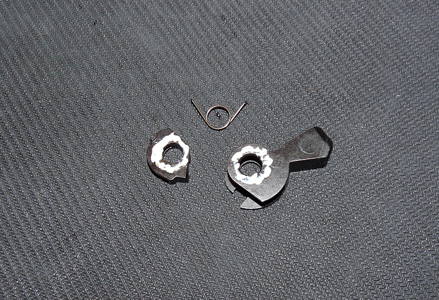
If you decide to purchase the V5+6 Detent Plate, make sure you get the right one because the HK45/HK45C series uses a different V5+6 Detent Plate. Below are pictures of the V5+6 Detent Plate for the USP/USPc series (left) and HK45/HK45C series (right).

Tools that you will need
• Dental Pick
• 1/16 Punch
• 3/32 Punch
• Thin, Long Needle-Nose Pliers
• Trigger Rebound Spring (TRS) Pliers from HKParts.net (optional but strongly recommended)

Step 1
• Insert the Overtravel Stop Screw on the Match Trigger
• To make it easier to install the screw, slave the Hex Wrench through the opening in the trigger and insert it into the screw.
• Turn the wrench counter-clockwise to install the screw
• It is important that you turn the stop screw all the way in and re-adjust it only when the installation is complete and you have verified that the hammer drops when trigger is pulled. Many people were having problem with the installation because the stop screw was not turned in all the way (e.g.: hammer does not drop when trigger is pulled because the stop screw is backed out too far)


Step 2
• While depressing on the Lanyard Block, push out the Lanyard Pin using the 3/32 punch
• Remove the Lanyard Pin, Lanyard Block, and Hammer Spring
Part identification:
1. Hammer Spring
2. Lanyard Block
3. Lanyard Pin


Step 3
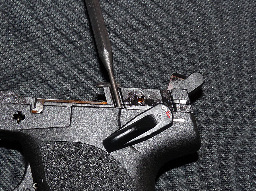
• Locate the Sear Axle (circled in RED)
• Use the 3/32 punch to push out the axle far enough so it sits flush on the frame
• Remove the Detent Plate


Step 4
• Now push the Sear Axle all the way out to the right side of the frame
• Remove the Disconnector > Catch > Control Latch > Sear (easier in that order)
Part identification:
1. Detent Plate
2. Sear Axle
3. Disconnector
4. Catch
5. Control Latch
6. Sear

Step 5
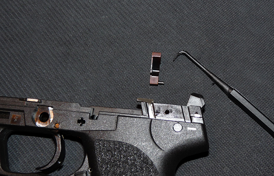
• Insert the 3/32 punch into the cavity right in front of the Safety Lever
• While depressing on the punch (which releases tension on the Slide Plate), rotate the Safety Lever to the 12-o'clock position
• Pull out the Safety Lever

Step 6
• Turn the frame upside down and shake it a couple of times. The Slide Plate and Slide Plate Compression Spring should fall out
Part identification:
1. Slide Plate Compression Spring
2. Slide Plate
3. Safety Lever

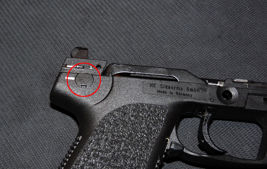
Step 7
• Insert the 3/32 punch into the safety lever hole (circled in RED) and push out the Hammer Axle towards the right side of the frame
• Remove the Hammer Axle and Hammer

Step 8
• Locate the Trigger Bar (right side of frame) and the Trigger Bar Detent (underneath the Trigger Bar)
• When removing the Trigger Bar, watch the detent as it is held under tension of the detent spring
• Rotate the Trigger Bar upward and remove it from the frame
• Turn the frame upside down and the Trigger Bar Detent should fall out

Step 9
• Turn the frame upside down and locate the Flat Sear Spring
• Use a small, flat-tipped screwdriver and push it against the small latch on the spring to unlock it from the frame (circled in RED)
• Flip the frame around and use the needle-nose pliers to grab the spring and remove it

Step 10
• Grab the Nickel-Plated Flat Sear Spring with the needle-nose pliers
• Insert the spring into the frame (the same spot where you had removed the stock spring in the previous step)


Step 11
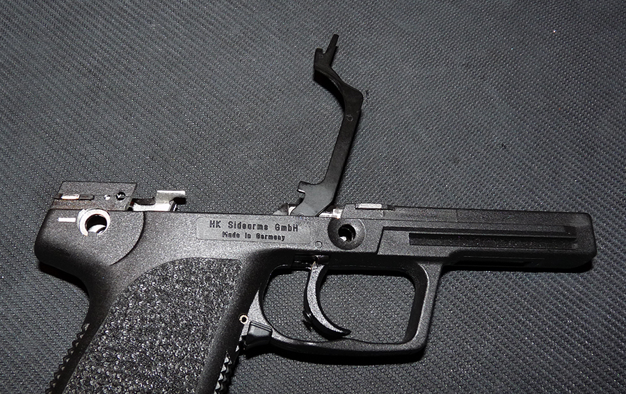
• The next step is to swap out the stock trigger with the Match Trigger
• Locate the Trigger Axle on the right side of the frame (right above the trigger, circled in RED)
• Use the 1/16 punch, push the trigger axle all the way out
• Grab the stock Trigger Rebound Spring (TRS) using the TRS Pliers and slowly back out the punch
• Remove the TRS and Trigger


Step 12
• Guide the Match Trigger into the opening in the frame (Did you remember to screw on the overtravel stop screw first?)
Step 13
• Insert the 1/16 punch into the trigger axle hole, but don't let the tip extend past the right side of the frame (to leave room for the TRS)
• Use the TRS pliers and grab the Light TRS as shown in the picture
• Insert the TRS so that the left leg of the spring rests upon the notch on the LEFT side of the frame, and the other leg rests squarely on the trigger
• Once the TRS is correctly inserted, push the punch all the way through to the left side of the frame
• Insert the Trigger Axle (from the left side) and push it in while backing out the punch slowly until the axle sits flush with the right side of the frame. The axle may not go in completely at first and may need a light tap with a punch to install it properly


• Verify that the Trigger Axle sits a little below the surface on the left side of the frame (circled in RED)

Step 14
• Drop the Trigger Bar Detent and Spring into the hole on the frame
• Mount the Trigger Bar onto the eyelet on the trigger by pulling sightly on the trigger (which rotates the eyelet towards the muzzle) and hooking the Trigger Bar onto the eyelet on the trigger
• Rotate the Trigger Bar down towards the rear of the frame. It rests on top of the Trigger Bar Detent
• If you push down on the Trigger Bar, there should be some tension from the Trigger Bar Detent


Step 15
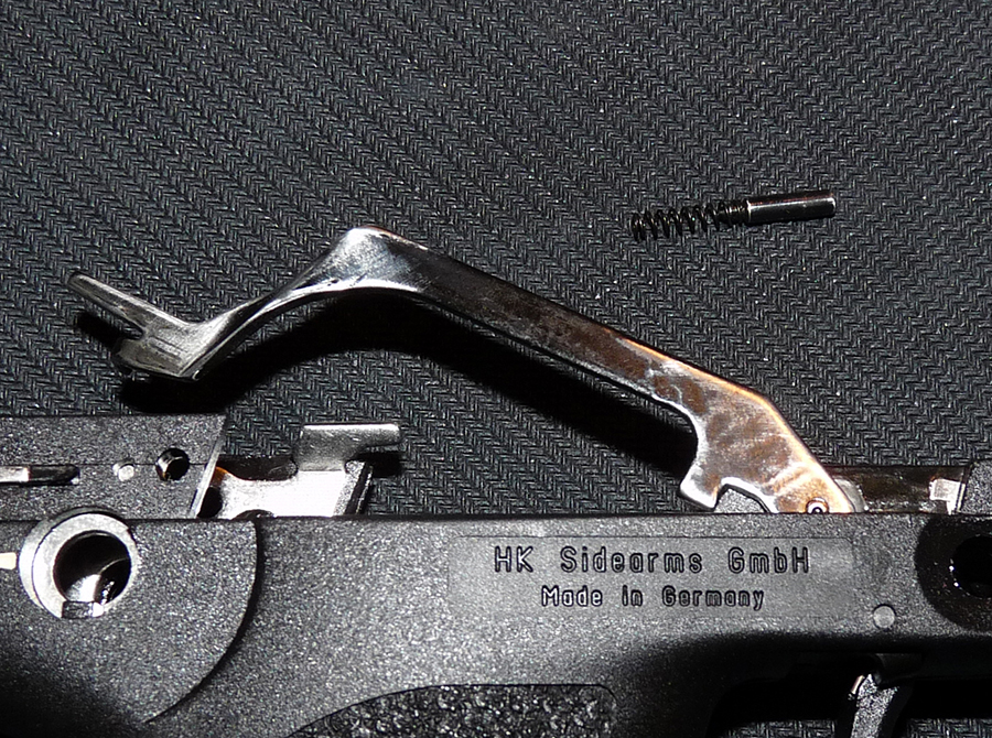
• Drop the Hammer Strut into the opening in the frame (below the hammer)


Step 16
• Assemble the Cocking Piece, Cocking Piece Spring, and LEM Hammer. Note the orientation of the Cocking Piece.
• Put a few dabs of grease/lubricant on the Cocking Piece and Hammer to make the assembly easier
Part identification:
1. Cocking Piece
2. Cocking Piece Spring
3. LEM Bobbed Hammer

Step 17
If you are going to keep the safety function, skip to step 18
• Use the LEM Hammer Axle for this step. It is best to lay the frame on its right side for easier installation
• Carefully guide the assembled LEM Hammer into the frame
• While depressing lightly on the Trigger Bar, guide the LEM Hammer Axle from the right side of the frame into the frame and through the assembled LEM Hammer
• Once completely inserted, the LEM Hammer Axle should sit flush with both sides of the frame (circled in RED)


Step 18
If you are not keeping the safety function, skip to step 19
• You are going to re-use the DA/SA Hammer Axle in this step. It is best to lay the frame on its right side for easier installation
• Carefully guide the assembled LEM Hammer into the frame
• While depressing lightly on the Trigger Bar, guide the LEM Hammer Axle from the right side of the frame into the frame and through the assembled LEM Hammer
• Once completely inserted, the LEM Hammer Axle should sit flush with the right side of the frame and completely hidden from the left side (circled in RED)


Step 19
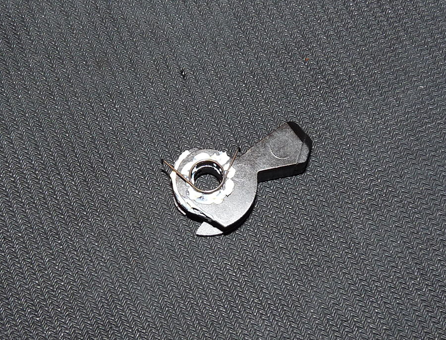
• Locate the legs of the Cocking Piece Spring
• Using the Dental Pick, grab both legs and pull them back towards the hammer
• While pulling back on the legs, insert the LEM Sear between the Flat Sear Spring and LEM Hammer. The back of the LEM Sear should be resting on the Flat Sear Spring (towards the muzzle)
• Let go of the Cocking Piece Spring legs and verify that one leg is resting on the hammer and the other is resting on the LEM Sear (circled in RED)

Step 20
If you are not keeping the safety function, skip to step 22
Part identification:
1. Slide Plate Compression Spring
2. Slide Plate
3. V5+6 Detent Plate (or V1+2 Detent Plate)

• Assemble the Slide Plate and Slide Plate Compression Spring as shown

• Insert the assembled Slide Plate into the cavity forward of the Safety Lever

• Using the 3/32 punch, push down on the Slide Plate so that it clears the Safety Lever/Hammer Axle opening
• While depressing the Slide Plate, insert the Safety Lever
• Remove the punch


Step 21
• Make sure the Sear Axle sits flush with the left side of the frame
• Slide the V5+6 Detent Plate (or V1+2)
• Push the Sear Axle back to the left side until it sits flush with the right side of the frame. This will lock the Detent Plate in place
• Function check the Safety Lever. If using the V5+6 Detent Plate, you should not be able to push down on the Safety Lever past the F position. If using V1+2, you will be able to push down on the Safety Lever past the F position (as if you are decocking). Either way, the decocking function is no longer working

Step 22
• Insert the Disconnector into the frame (right side, next to the Trigger Bar)
• Assemble the Catch and Control Latch as shown, and insert them into the gap between the Disconnector and LEM Hammer
Part identification:
1. Disconnector
2. Control Latch
3. Catch


Step 23
• Slave the 3/32 punch through the Disconnector, Control Latch, Catch, and LEM Sear as shown
• Insert the Sear Axle from the left side of the frame, slowly backing out the punch until it sits flush with the right side of the frame


Step 24
• Verify that the Sear Axle sits flush with the right side of the frame (and protrudes slightly from the left side of the frame)


Step 25
• Drop the Match Hammer Spring onto the Hammer Strut
• Install the Lanyard Block and while depressing lightly on the Lanyard Block, insert the Lanyard Pin to secure it
Part identification:
1. Match Hammer Spring
2. Lanyard Block
3. Lanyard Pin


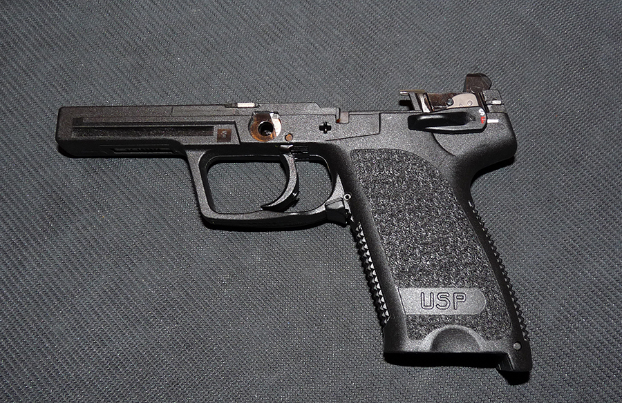
Your Match LEM Hybrid Trigger installation is now complete!
Match LEM Hybrid Trigger without safety
Match LEM Hybrid Trigger with safety

The same guide can be used to install the kit on a USP Compact, HK45, or HK45 Compact. Note that if you are installing the kit on a compact or HK45, you will not be able to use the trigger that comes with the Match Trigger kit. In addition, there is very little room behind the trigger on the compacts so the overtravel screw does not help. To install the Match trigger on a full-size HK45, you will have to drill and tap the stock trigger to fit the overtravel stop screw, or shave down the trigger to fit. You can also send your stock trigger to Bill Springfield to have it drilled and tapped for $20. Bill will provide a stop screw with the service.
Parts can be purchased directly from HK Customer Service (706-568-1906, press 1 for Consumer Support, then 2 to order parts), Cross Creek Guns, Numrich, HKParts.net, TopGunSupply, Midwestgunworks, Brownells, EuroOptic, or other online vendors. It will be most cost effective to purchase the complete LEM Kit and only parts of the Match Trigger Kit (not the complete Match Trigger Kit) because you will not be using the Match hammer and it is the most expensive part of the Match Trigger Kit.
If you reside within the state of Texas and would like to perform this conversion but feel uneasy about taking apart the pistol and putting everything back together, send me a PM. I might be able to offer some assistance.
Important Notes
• If you are installing the kit on an older model USP Compact or HK45 (date code of BB=2012 or earlier), you may not need to swap out the stock hammer spring as their stock hammer spring is the Match spring. Later models of these 2 guns no longer come with the Match hammer spring. The easiest way to tell if your gun has the Match hammer spring is to remove the magazine and look at the existing hammer spring in the magwell. If it is Blue (see pic below), you do not have the Match spring.
• If your gun is already a LEM (Heavy or Light), you will not need parts 7 thru 12 in the picture below.
• If your gun already has the Match trigger (e.g.: Tactical, Expert, Elite, etc.) then you will only need parts 8 thru 12 (or the complete LEM kit) and part 7 if your date code is pre 2005 (AF). You may need parts 5 and 6 on newer Tactical models.
Parts Required
1. Match Trigger (215684)
2. Overtravel Stop Screw (215680)
3. Hex Wrench for Stop Screw (958179)
4. Light TRS (209266)
5. Match Hammer Spring (215694)
6. Match Nickel-Plated Flat Sear Spring (215691)
7. Catch (219442 - only needed if your gun's date code is early AF=2005 or earlier)
8. LEM Sear (219439)
9. LEM Hammer (219452)
10. LEM Cocking Piece (219443)
11. LEM Cocking Piece Spring (219444)
12. LEM Hammer Axle (214258)
If you want to retain the safety function (and thus the Safety Lever), you will need a V5+6 Detent Plate (or re-use your stock V1+2 Detent Plate.) If using the V5+6 Detent Plate, you will not be able to push down on the Safety Lever past the F position (as if you are decocking). Either way, the decocking function no longer works when you convert your DA/SA gun to Match LEM Hybrid Trigger (or LEM in general).
If you decide to purchase the V5+6 Detent Plate, make sure you get the right one because the HK45/HK45C series uses a different V5+6 Detent Plate. Below are pictures of the V5+6 Detent Plate for the USP/USPc series (left) and HK45/HK45C series (right).
Tools that you will need
• Dental Pick
• 1/16 Punch
• 3/32 Punch
• Thin, Long Needle-Nose Pliers
• Trigger Rebound Spring (TRS) Pliers from HKParts.net (optional but strongly recommended)
Step 1
• Insert the Overtravel Stop Screw on the Match Trigger
• To make it easier to install the screw, slave the Hex Wrench through the opening in the trigger and insert it into the screw.
• Turn the wrench counter-clockwise to install the screw
• It is important that you turn the stop screw all the way in and re-adjust it only when the installation is complete and you have verified that the hammer drops when trigger is pulled. Many people were having problem with the installation because the stop screw was not turned in all the way (e.g.: hammer does not drop when trigger is pulled because the stop screw is backed out too far)
Step 2
• While depressing on the Lanyard Block, push out the Lanyard Pin using the 3/32 punch
• Remove the Lanyard Pin, Lanyard Block, and Hammer Spring
Part identification:
1. Hammer Spring
2. Lanyard Block
3. Lanyard Pin
Step 3
• Locate the Sear Axle (circled in RED)
• Use the 3/32 punch to push out the axle far enough so it sits flush on the frame
• Remove the Detent Plate
Step 4
• Now push the Sear Axle all the way out to the right side of the frame
• Remove the Disconnector > Catch > Control Latch > Sear (easier in that order)
Part identification:
1. Detent Plate
2. Sear Axle
3. Disconnector
4. Catch
5. Control Latch
6. Sear
Step 5
• Insert the 3/32 punch into the cavity right in front of the Safety Lever
• While depressing on the punch (which releases tension on the Slide Plate), rotate the Safety Lever to the 12-o'clock position
• Pull out the Safety Lever
Step 6
• Turn the frame upside down and shake it a couple of times. The Slide Plate and Slide Plate Compression Spring should fall out
Part identification:
1. Slide Plate Compression Spring
2. Slide Plate
3. Safety Lever
Step 7
• Insert the 3/32 punch into the safety lever hole (circled in RED) and push out the Hammer Axle towards the right side of the frame
• Remove the Hammer Axle and Hammer
Step 8
• Locate the Trigger Bar (right side of frame) and the Trigger Bar Detent (underneath the Trigger Bar)
• When removing the Trigger Bar, watch the detent as it is held under tension of the detent spring
• Rotate the Trigger Bar upward and remove it from the frame
• Turn the frame upside down and the Trigger Bar Detent should fall out
Step 9
• Turn the frame upside down and locate the Flat Sear Spring
• Use a small, flat-tipped screwdriver and push it against the small latch on the spring to unlock it from the frame (circled in RED)
• Flip the frame around and use the needle-nose pliers to grab the spring and remove it
Step 10
• Grab the Nickel-Plated Flat Sear Spring with the needle-nose pliers
• Insert the spring into the frame (the same spot where you had removed the stock spring in the previous step)
Step 11
• The next step is to swap out the stock trigger with the Match Trigger
• Locate the Trigger Axle on the right side of the frame (right above the trigger, circled in RED)
• Use the 1/16 punch, push the trigger axle all the way out
• Grab the stock Trigger Rebound Spring (TRS) using the TRS Pliers and slowly back out the punch
• Remove the TRS and Trigger
Step 12
• Guide the Match Trigger into the opening in the frame (Did you remember to screw on the overtravel stop screw first?)
Step 13
• Insert the 1/16 punch into the trigger axle hole, but don't let the tip extend past the right side of the frame (to leave room for the TRS)
• Use the TRS pliers and grab the Light TRS as shown in the picture
• Insert the TRS so that the left leg of the spring rests upon the notch on the LEFT side of the frame, and the other leg rests squarely on the trigger
• Once the TRS is correctly inserted, push the punch all the way through to the left side of the frame
• Insert the Trigger Axle (from the left side) and push it in while backing out the punch slowly until the axle sits flush with the right side of the frame. The axle may not go in completely at first and may need a light tap with a punch to install it properly
• Verify that the Trigger Axle sits a little below the surface on the left side of the frame (circled in RED)
Step 14
• Drop the Trigger Bar Detent and Spring into the hole on the frame
• Mount the Trigger Bar onto the eyelet on the trigger by pulling sightly on the trigger (which rotates the eyelet towards the muzzle) and hooking the Trigger Bar onto the eyelet on the trigger
• Rotate the Trigger Bar down towards the rear of the frame. It rests on top of the Trigger Bar Detent
• If you push down on the Trigger Bar, there should be some tension from the Trigger Bar Detent
Step 15
• Drop the Hammer Strut into the opening in the frame (below the hammer)
Step 16
• Assemble the Cocking Piece, Cocking Piece Spring, and LEM Hammer. Note the orientation of the Cocking Piece.
• Put a few dabs of grease/lubricant on the Cocking Piece and Hammer to make the assembly easier
Part identification:
1. Cocking Piece
2. Cocking Piece Spring
3. LEM Bobbed Hammer
Step 17
If you are going to keep the safety function, skip to step 18
• Use the LEM Hammer Axle for this step. It is best to lay the frame on its right side for easier installation
• Carefully guide the assembled LEM Hammer into the frame
• While depressing lightly on the Trigger Bar, guide the LEM Hammer Axle from the right side of the frame into the frame and through the assembled LEM Hammer
• Once completely inserted, the LEM Hammer Axle should sit flush with both sides of the frame (circled in RED)
Step 18
If you are not keeping the safety function, skip to step 19
• You are going to re-use the DA/SA Hammer Axle in this step. It is best to lay the frame on its right side for easier installation
• Carefully guide the assembled LEM Hammer into the frame
• While depressing lightly on the Trigger Bar, guide the LEM Hammer Axle from the right side of the frame into the frame and through the assembled LEM Hammer
• Once completely inserted, the LEM Hammer Axle should sit flush with the right side of the frame and completely hidden from the left side (circled in RED)
Step 19
• Locate the legs of the Cocking Piece Spring
• Using the Dental Pick, grab both legs and pull them back towards the hammer
• While pulling back on the legs, insert the LEM Sear between the Flat Sear Spring and LEM Hammer. The back of the LEM Sear should be resting on the Flat Sear Spring (towards the muzzle)
• Let go of the Cocking Piece Spring legs and verify that one leg is resting on the hammer and the other is resting on the LEM Sear (circled in RED)
Step 20
If you are not keeping the safety function, skip to step 22
Part identification:
1. Slide Plate Compression Spring
2. Slide Plate
3. V5+6 Detent Plate (or V1+2 Detent Plate)
• Assemble the Slide Plate and Slide Plate Compression Spring as shown
• Insert the assembled Slide Plate into the cavity forward of the Safety Lever
• Using the 3/32 punch, push down on the Slide Plate so that it clears the Safety Lever/Hammer Axle opening
• While depressing the Slide Plate, insert the Safety Lever
• Remove the punch
Step 21
• Make sure the Sear Axle sits flush with the left side of the frame
• Slide the V5+6 Detent Plate (or V1+2)
• Push the Sear Axle back to the left side until it sits flush with the right side of the frame. This will lock the Detent Plate in place
• Function check the Safety Lever. If using the V5+6 Detent Plate, you should not be able to push down on the Safety Lever past the F position. If using V1+2, you will be able to push down on the Safety Lever past the F position (as if you are decocking). Either way, the decocking function is no longer working
Step 22
• Insert the Disconnector into the frame (right side, next to the Trigger Bar)
• Assemble the Catch and Control Latch as shown, and insert them into the gap between the Disconnector and LEM Hammer
Part identification:
1. Disconnector
2. Control Latch
3. Catch
Step 23
• Slave the 3/32 punch through the Disconnector, Control Latch, Catch, and LEM Sear as shown
• Insert the Sear Axle from the left side of the frame, slowly backing out the punch until it sits flush with the right side of the frame
Step 24
• Verify that the Sear Axle sits flush with the right side of the frame (and protrudes slightly from the left side of the frame)
Step 25
• Drop the Match Hammer Spring onto the Hammer Strut
• Install the Lanyard Block and while depressing lightly on the Lanyard Block, insert the Lanyard Pin to secure it
Part identification:
1. Match Hammer Spring
2. Lanyard Block
3. Lanyard Pin
Your Match LEM Hybrid Trigger installation is now complete!
Match LEM Hybrid Trigger without safety
Match LEM Hybrid Trigger with safety
