This multi-part guide will show you how to detail strip an H&K VP9.
Part 1 - Frame Disassembly
Tools your will need
• 1.8mm punch (or 1/16")
• 2.4mm punch (or 3/32")
• 2.8mm punch (or 7/64")
• Trigger Rebound Spring (TRS) Tool (sold on HKParts)
• A bench block (optional)
• Small hammer or mallet

Step 1
• Make sure gun is unloaded. Check and check again!
• Remove the slide
• Leave the Disassembly Lever in the downward position
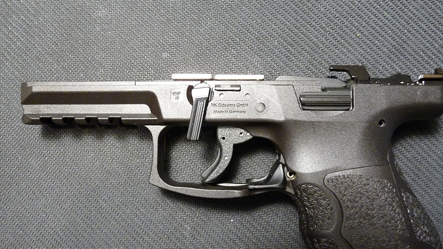
Step 2
• Rotate the Disassembly Lever towards the front of the muzzle about 10-15 degrees
• Lift and pull the lever out of the frame


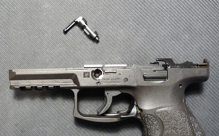
Step 3
• Make note of the position of the Trigger Round Spring (TRS) legs. The right leg is resting on the frame while the left leg is resting against the top of the trigger.
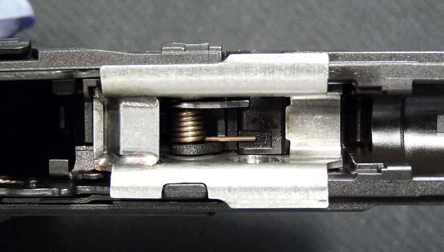

Step 4
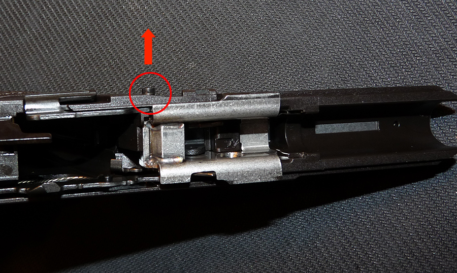
• Locate the Safety Clamp on the right side of the frame
• Using a punch, push it up and out of the frame


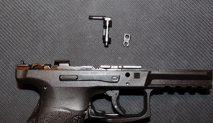
Step 5
• Wiggle the Right-Side Slide Release Lever (up-and-down motion) and pull it out of the frame. Cover the TRS area with your hand before removing the Slide Release Lever because as soon as you pull out the lever, the TRS will come flying out. You do not want to misplace this spring!

Step 6
• Remove the TRS

Step 7
• Locate the Disconnector. It sits between the frame (right side) and the Trigger Bar
• Lift it up and remove it from the frame
Parts identification
1. Disconnector
2. Disassembly Lever
3. Safety Clamp
4. TRS
5. Right-Side Slide Release Lever

Step 8
• Lay the frame on its left side and locate the Roll-Pin and the Clamping Sleeve for the Locking Block. Note that the Roll-Pin sits inside the Clamping Sleeve
• Using the 2.8mm (7/64") punch, drive out both the Roll-Pin and the Clamping Sleeve. It might be easier to punch out the Roll-Pin first, followed by the Clamping Sleeve.

Step 9
• Look inside the Locking Block and locate the Trigger Stop Bolt
• Using a small punch, push out the bolt (to the left side of the frame)
• Remove the bolt from the frame


Step 10
• Lift up the Locking Block and remove it from the frame
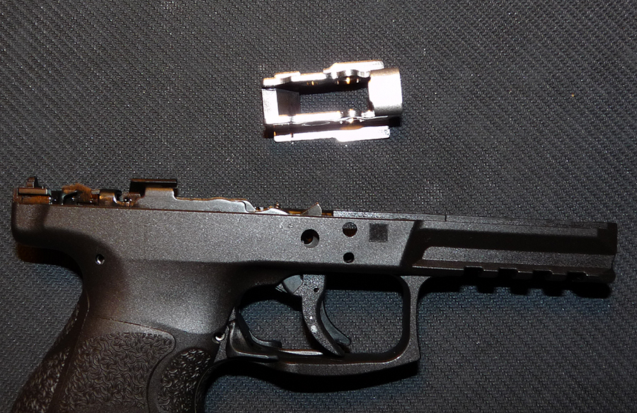
Step 11
• Locate the Left-Side Slide Release Lever and its spring. Remove both from the frame

Step 12
• Remove the Dismounting Safety and its spring from the Locking Block


Step 13
• Find the Catch Spring for Disassembly Lever on the right side of the frame
• Lift it up and remove it from the frame

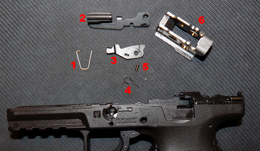
Parts identifcation
1. Catch Spring for Disassembly Lever
2. Left-Side Slide Release Lever
3. Dismounting Safety
4. Elbow Spring for Dismounting Safety
5. Left-Side Slide Release Lever Spring
6. Locking Block
Step 14
• Make note of where the Trigger Bar Spring mounts on the frame
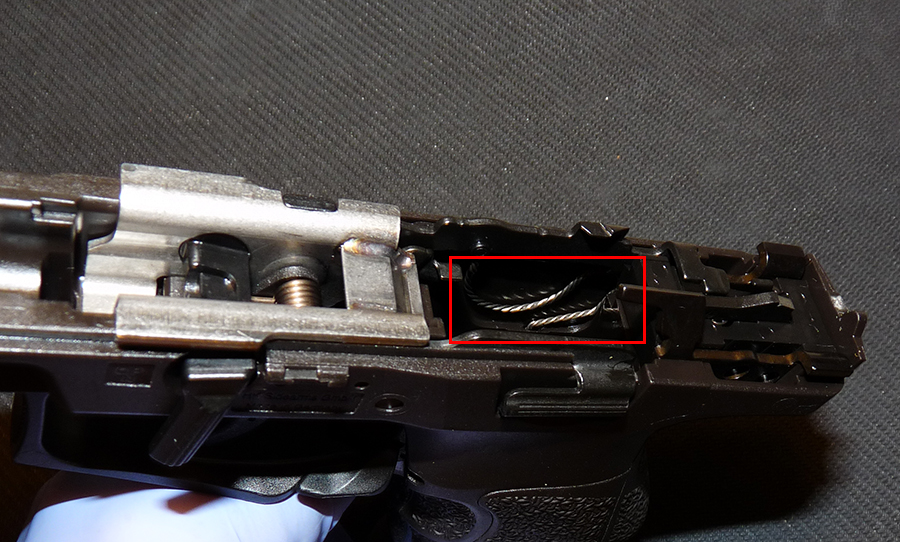
• Lift up the Trigger Bar and remove it from the frame


Step 15
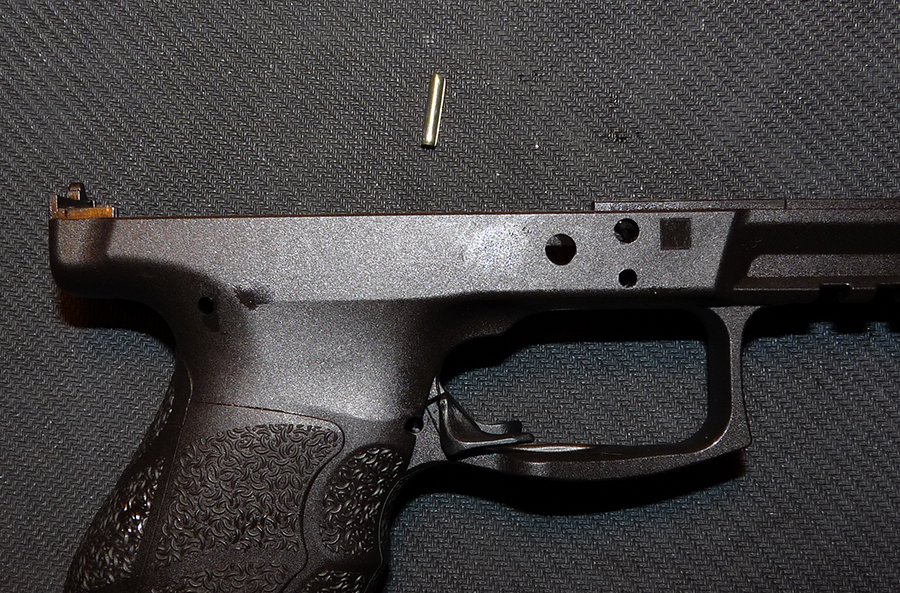
• Locate the Clamping Sleeve for Trigger Housing (top of the grip area)
• Using the 2.8mm (7/64") punch, drive out the Clamping Sleeve


Step 16
• Lift up and remove the Trigger Housing from the frame
Parts identification
1. Trigger Housing (complete)
2. Roll pin

Step 17
• Locate the roll-pin for Magazine Release Lever
• Using the 2.4mm (3/32") punch, drive out the roll-pin

Step 18
• Wiggle the Magazine Release Lever out of the frame. Watch out for the flying spring
Parts identification
1. Magazine Release Lever
2. Roll-pin
3. Spring

Step 19
• Locate the Backstrap roll-pin
• Using the 2.4mm (3/32") punch, drive out the roll-pin
• Remove the Backstrap


Your frame is now completely disassembled!

Parts identification
1. Locking Block
2. Left-Side Slide Release Lever
3. Left-Side Slide Release Lever Spring
4. Catch Spring for Disassembly Lever
5. Safety Clamp
6. TRS
7. Clamping Sleeve (with Roll-Pin) for Locking Block
9. Right-Side Slide Release Lever
10. Disassembly Lever
11. Trigger and Trigger Bar (complete)
12. Trigger Stop Bolt
13. Elbow Spring for Dismounting Safety
14. Dismounting Safety
15. Disconnector
16. Trigger Housing (complete)
17. Clamping Sleeve for Trigger Housing
18. Magazine Release Lever
19. Roll-pin for Magazine Release Lever
20. Magazine Release Lever Spring

Part 1 - Frame Disassembly
Tools your will need
• 1.8mm punch (or 1/16")
• 2.4mm punch (or 3/32")
• 2.8mm punch (or 7/64")
• Trigger Rebound Spring (TRS) Tool (sold on HKParts)
• A bench block (optional)
• Small hammer or mallet
Step 1
• Make sure gun is unloaded. Check and check again!
• Remove the slide
• Leave the Disassembly Lever in the downward position
Step 2
• Rotate the Disassembly Lever towards the front of the muzzle about 10-15 degrees
• Lift and pull the lever out of the frame
Step 3
• Make note of the position of the Trigger Round Spring (TRS) legs. The right leg is resting on the frame while the left leg is resting against the top of the trigger.
Step 4
• Locate the Safety Clamp on the right side of the frame
• Using a punch, push it up and out of the frame
Step 5
• Wiggle the Right-Side Slide Release Lever (up-and-down motion) and pull it out of the frame. Cover the TRS area with your hand before removing the Slide Release Lever because as soon as you pull out the lever, the TRS will come flying out. You do not want to misplace this spring!
Step 6
• Remove the TRS
Step 7
• Locate the Disconnector. It sits between the frame (right side) and the Trigger Bar
• Lift it up and remove it from the frame
Parts identification
1. Disconnector
2. Disassembly Lever
3. Safety Clamp
4. TRS
5. Right-Side Slide Release Lever
Step 8
• Lay the frame on its left side and locate the Roll-Pin and the Clamping Sleeve for the Locking Block. Note that the Roll-Pin sits inside the Clamping Sleeve
• Using the 2.8mm (7/64") punch, drive out both the Roll-Pin and the Clamping Sleeve. It might be easier to punch out the Roll-Pin first, followed by the Clamping Sleeve.
Step 9
• Look inside the Locking Block and locate the Trigger Stop Bolt
• Using a small punch, push out the bolt (to the left side of the frame)
• Remove the bolt from the frame
Step 10
• Lift up the Locking Block and remove it from the frame
Step 11
• Locate the Left-Side Slide Release Lever and its spring. Remove both from the frame
Step 12
• Remove the Dismounting Safety and its spring from the Locking Block
Step 13
• Find the Catch Spring for Disassembly Lever on the right side of the frame
• Lift it up and remove it from the frame
Parts identifcation
1. Catch Spring for Disassembly Lever
2. Left-Side Slide Release Lever
3. Dismounting Safety
4. Elbow Spring for Dismounting Safety
5. Left-Side Slide Release Lever Spring
6. Locking Block
Step 14
• Make note of where the Trigger Bar Spring mounts on the frame
• Lift up the Trigger Bar and remove it from the frame
Step 15
• Locate the Clamping Sleeve for Trigger Housing (top of the grip area)
• Using the 2.8mm (7/64") punch, drive out the Clamping Sleeve
Step 16
• Lift up and remove the Trigger Housing from the frame
Parts identification
1. Trigger Housing (complete)
2. Roll pin
Step 17
• Locate the roll-pin for Magazine Release Lever
• Using the 2.4mm (3/32") punch, drive out the roll-pin
Step 18
• Wiggle the Magazine Release Lever out of the frame. Watch out for the flying spring
Parts identification
1. Magazine Release Lever
2. Roll-pin
3. Spring
Step 19
• Locate the Backstrap roll-pin
• Using the 2.4mm (3/32") punch, drive out the roll-pin
• Remove the Backstrap
Your frame is now completely disassembled!
Parts identification
1. Locking Block
2. Left-Side Slide Release Lever
3. Left-Side Slide Release Lever Spring
4. Catch Spring for Disassembly Lever
5. Safety Clamp
6. TRS
7. Clamping Sleeve (with Roll-Pin) for Locking Block
9. Right-Side Slide Release Lever
10. Disassembly Lever
11. Trigger and Trigger Bar (complete)
12. Trigger Stop Bolt
13. Elbow Spring for Dismounting Safety
14. Dismounting Safety
15. Disconnector
16. Trigger Housing (complete)
17. Clamping Sleeve for Trigger Housing
18. Magazine Release Lever
19. Roll-pin for Magazine Release Lever
20. Magazine Release Lever Spring

