Part 2 - Frame Reassembly
Step 1
• Insert the Magazine Release Lever Spring into the Magazine Release Lever
• Carefully insert the lever into the frame. It needs a little wiggle to get it sit properly. Use a small butter knife/blade to compress the spring when sliding it in

Step 2
• Using the 2.4mm (3/32") punch, while applying a little downward pressure on the lever, tap in the roll-pin until it sits slightly below the surface

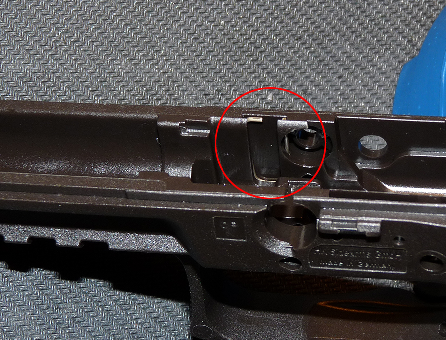
Step 3
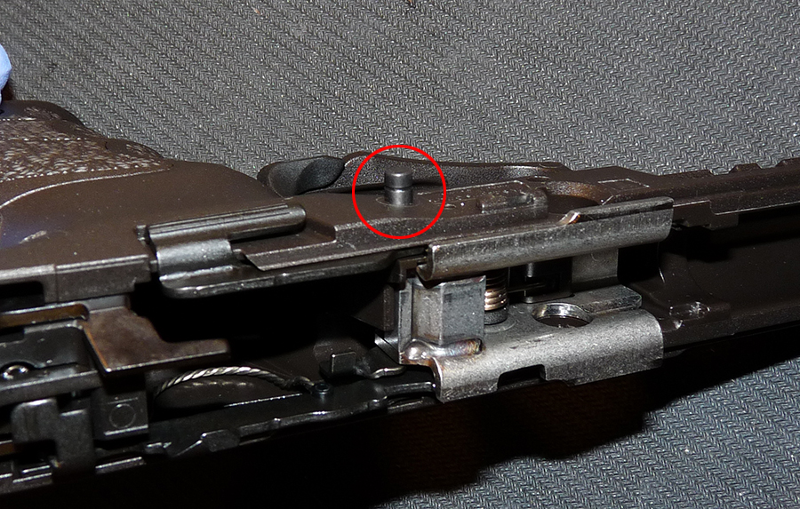
• Insert the complete Trigger Housing into the frame, making sure the rear of the housing is pushed up against the back of the frame
• Check to make sure the tang on the housing is visible in the little cut-out on the frame (circled in Red)
• If the housing is not positioned correctly, the roll-pin hole on the housing will not line up properly with the hole on the frame


Step 4
• Make sure the roll-pin hole on the Trigger Housing is lined up correctly with the roll-pin hole on the frame (circled in Red)
• Make sure you're using the correct Clamping Sleeve. There are 2 long Clamping Sleeves, one for the Locking Block and one for the Trigger Housing. The one for the Trigger Housing is the shorter one and the one for the Locking Block has a Roll-Pin tucked inside
• Temporarily insert the Trigger Housing Clamping Sleeve into the frame and, using the 2/8mm (7/64") punch, drive it in

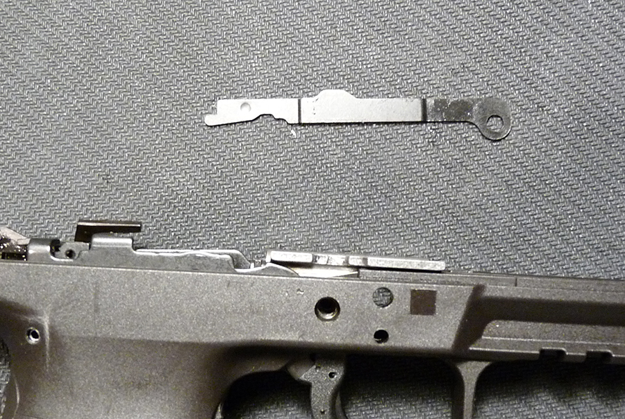
Step 5
• Insert the Catch Spring for Disassembly Lever into the slot on the right side of the frame. Note the orientation of the spring
• Make sure it is positioned correctly on the frame

Step 6
• Lay the Locking Block on its side, as shown in the picture
• Locate the indentation on the Locking Block where the Catch Spring for Dismounting Safety will be mounted

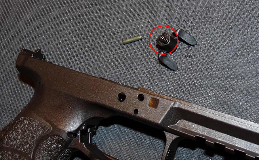
Step 7
• Mount the spring inside the indentation on the Locking Block as shown. The longer leg of the spring points downward
• Note the small hook on the Dismounting Safety (circled in Red). When the Dismounting Safety is flipped over and mounted on the Locking Block, the longer leg of the Catch Spring will rest on the upper side of this hook

Step 8
• Flip the Dismounting Safety over and carefully mount it on the Locking Block, laying on top of the Catch Spring
• Note how the spring is compressed and where the leg of the spring is positioned above the hook on the Dismounting Safety
• To check if the Dismounting Safety is mounted correctly, push up on the safety and you should feel a little tension


Step 9
• Drop in the Trigger Bar (with complete Trigger) and carefully slide it into place

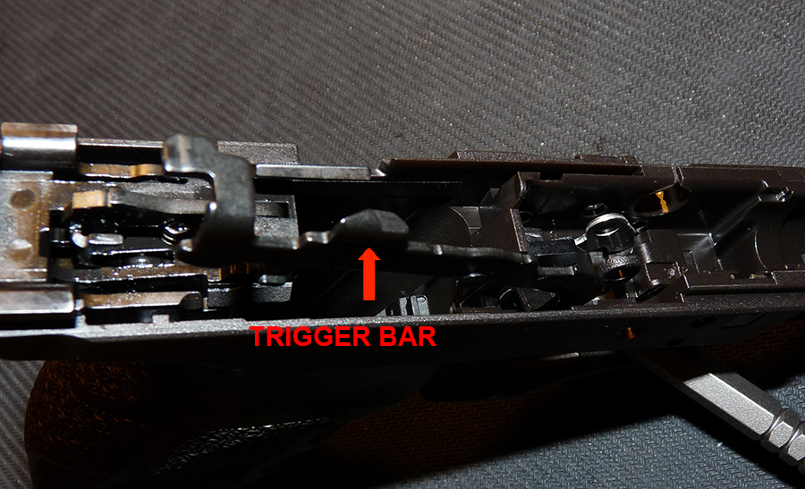
• Tuck the other end of the Trigger Bar Spring into the cavity on the frame
• Note how the Trigger Bar Spring is mounted on the frame

Step 10
• Mount the left-side Slide Release Lever onto the frame
• Note the notch on the lever for the Pressure Spring


Step 11
• Locate the notch on the left-side Slide Release Lever where the Pressure Spring will be positioned (circled in Red)
• Drop in the spring


Step 12
• Drop in the Locking Block, making sure the Dismounting Safety does not fall off while inserting the Locking Block into the frame
• Make sure the Trigger is positioned inside the Locking Block

Step 13
• Insert the Disconnector into the frame. It will go to the right of the Trigger Bar, against the right side of the frame
• Note the location of the Disconnector and Trigger Bar in relation to the Dismounting Safety


Step 14
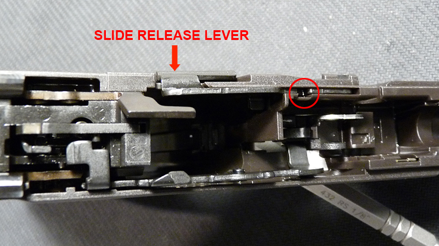
• Line up the Disconnector, Trigger Bar, Locking Block and insert the right-side Slide Release Lever
• Insert the lever just enough so it protrudes slightly past the inside wall of the Locking Block (to leave room for the insertion of the TRS in the next step)


Step 15
• There are 2 eyelets on the trigger itself. In the picture below, note the bare-metal color eyelet (the one located on the left-side of the trigger) and the other in black color.

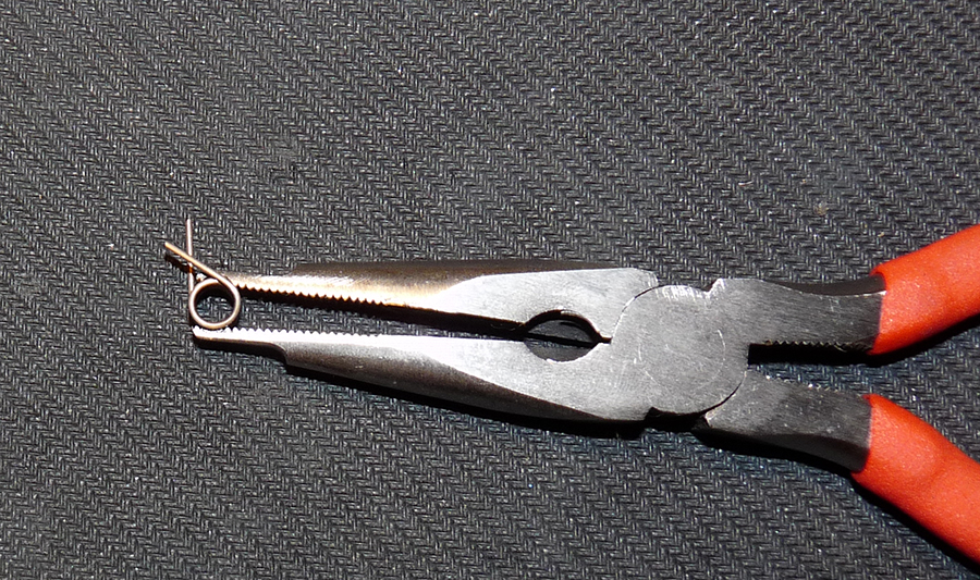
• Grab the Trigger Rebound Spring (TRS) using the HKParts TRS Tool as shown and insert it into the Locking Block with a little downward pressure

• Pay attention to the position of the legs of the TRS. The left leg rests upon the frame while the right leg rests against the top of the trigger, right up against the right side of that bare-metal color eyelet


• A close-up picture showing the position of the right leg of the TRS. For orientation purposes, the left side of the picture is facing the muzzle end of the frame

Step 16
• Push the right-side Slide Release Lever all the way in and through the TRS. It should lay flat against the right side of the frame
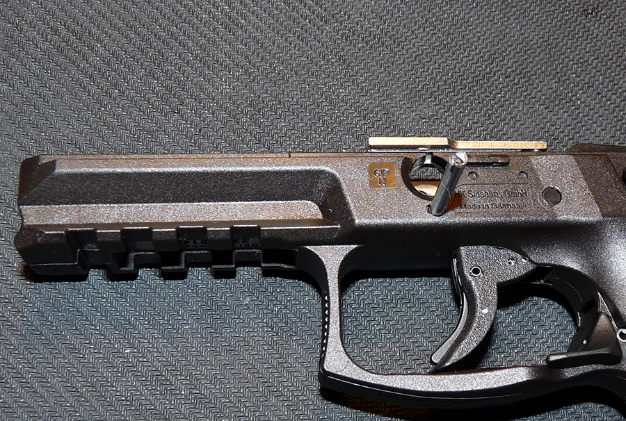
• Insert the Trigger Stop Bolt into the frame as shown
• Push it in until it sits slightly below the frame


Step 17
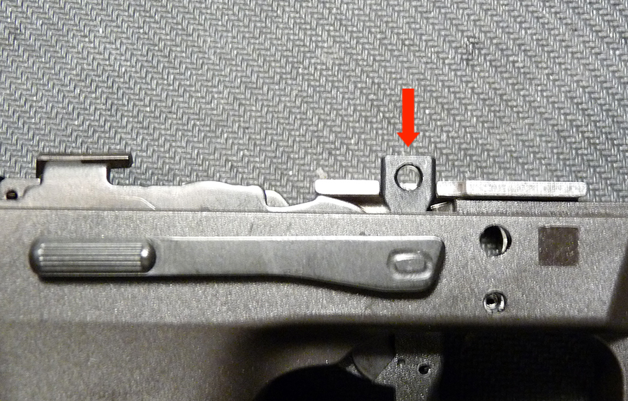
• Locate the roll-pin hole for the Locking Block on the frame (circled in Red)
• Using the 2.8mm (7/64") punch, drive in the Clamping Sleeve (with Roll-Pin)

Step 18
• Insert the Safety Clamp into the frame
• When fully seated, the clamp should sit flush with the top of the Locking Block


Step 19
• Insert the Disassembly Lever into the frame


Your frame is now completely reassembled!
Step 1
• Insert the Magazine Release Lever Spring into the Magazine Release Lever
• Carefully insert the lever into the frame. It needs a little wiggle to get it sit properly. Use a small butter knife/blade to compress the spring when sliding it in
Step 2
• Using the 2.4mm (3/32") punch, while applying a little downward pressure on the lever, tap in the roll-pin until it sits slightly below the surface
Step 3
• Insert the complete Trigger Housing into the frame, making sure the rear of the housing is pushed up against the back of the frame
• Check to make sure the tang on the housing is visible in the little cut-out on the frame (circled in Red)
• If the housing is not positioned correctly, the roll-pin hole on the housing will not line up properly with the hole on the frame
Step 4
• Make sure the roll-pin hole on the Trigger Housing is lined up correctly with the roll-pin hole on the frame (circled in Red)
• Make sure you're using the correct Clamping Sleeve. There are 2 long Clamping Sleeves, one for the Locking Block and one for the Trigger Housing. The one for the Trigger Housing is the shorter one and the one for the Locking Block has a Roll-Pin tucked inside
• Temporarily insert the Trigger Housing Clamping Sleeve into the frame and, using the 2/8mm (7/64") punch, drive it in
Step 5
• Insert the Catch Spring for Disassembly Lever into the slot on the right side of the frame. Note the orientation of the spring
• Make sure it is positioned correctly on the frame
Step 6
• Lay the Locking Block on its side, as shown in the picture
• Locate the indentation on the Locking Block where the Catch Spring for Dismounting Safety will be mounted
Step 7
• Mount the spring inside the indentation on the Locking Block as shown. The longer leg of the spring points downward
• Note the small hook on the Dismounting Safety (circled in Red). When the Dismounting Safety is flipped over and mounted on the Locking Block, the longer leg of the Catch Spring will rest on the upper side of this hook
Step 8
• Flip the Dismounting Safety over and carefully mount it on the Locking Block, laying on top of the Catch Spring
• Note how the spring is compressed and where the leg of the spring is positioned above the hook on the Dismounting Safety
• To check if the Dismounting Safety is mounted correctly, push up on the safety and you should feel a little tension
Step 9
• Drop in the Trigger Bar (with complete Trigger) and carefully slide it into place
• Tuck the other end of the Trigger Bar Spring into the cavity on the frame
• Note how the Trigger Bar Spring is mounted on the frame
Step 10
• Mount the left-side Slide Release Lever onto the frame
• Note the notch on the lever for the Pressure Spring
Step 11
• Locate the notch on the left-side Slide Release Lever where the Pressure Spring will be positioned (circled in Red)
• Drop in the spring
Step 12
• Drop in the Locking Block, making sure the Dismounting Safety does not fall off while inserting the Locking Block into the frame
• Make sure the Trigger is positioned inside the Locking Block
Step 13
• Insert the Disconnector into the frame. It will go to the right of the Trigger Bar, against the right side of the frame
• Note the location of the Disconnector and Trigger Bar in relation to the Dismounting Safety
Step 14
• Line up the Disconnector, Trigger Bar, Locking Block and insert the right-side Slide Release Lever
• Insert the lever just enough so it protrudes slightly past the inside wall of the Locking Block (to leave room for the insertion of the TRS in the next step)
Step 15
• There are 2 eyelets on the trigger itself. In the picture below, note the bare-metal color eyelet (the one located on the left-side of the trigger) and the other in black color.
• Grab the Trigger Rebound Spring (TRS) using the HKParts TRS Tool as shown and insert it into the Locking Block with a little downward pressure
• Pay attention to the position of the legs of the TRS. The left leg rests upon the frame while the right leg rests against the top of the trigger, right up against the right side of that bare-metal color eyelet
• A close-up picture showing the position of the right leg of the TRS. For orientation purposes, the left side of the picture is facing the muzzle end of the frame
Step 16
• Push the right-side Slide Release Lever all the way in and through the TRS. It should lay flat against the right side of the frame
• Insert the Trigger Stop Bolt into the frame as shown
• Push it in until it sits slightly below the frame
Step 17
• Locate the roll-pin hole for the Locking Block on the frame (circled in Red)
• Using the 2.8mm (7/64") punch, drive in the Clamping Sleeve (with Roll-Pin)
Step 18
• Insert the Safety Clamp into the frame
• When fully seated, the clamp should sit flush with the top of the Locking Block
Step 19
• Insert the Disassembly Lever into the frame
Your frame is now completely reassembled!
